Date:2025-05-21
/Update:2026-02-22
Sound Learning for Field Recording / Part 2: Understanding Recording and Signal Processing
In field recording, deciding where to point the microphone, which equipment to use, and what settings to apply requires a combination of both acoustic engineering knowledge and empirical experience.

Sound Learning for Field Recording
Following Part 1: Understanding the Basics of Sound, this second installment systematically covers the characteristics of recording equipment, considerations during recording, and the basics of digital audio processing.
Types of Microphones and How to Choose Them
Microphone Types and Mechanisms
Microphones convert sound into electrical signals using various methods. The two most representative types are Condenser and Dynamic microphones. Their differences are as follows:
Condenser Microphones
- High sensitivity and wide frequency response.
- Ideal for capturing delicate sounds and subtle details.
- Requires a power supply; battery-powered models are convenient.
- Sensitive design makes them vulnerable to humidity; require careful handling.
Dynamic Microphones
- Characterized by high durability and suppression of handling noise.
- High sound quality, but generally lacks the wide frequency response of condensers.
- Resistant to high sound pressure and robust against external elements like wind and rain.
In field recording, where delicate sounds are often the focus, condenser microphones are primarily used. Additionally, there are specialized microphones such as Hydrophones (for underwater) and Contact Microphones (for vibration in solids) alongside standard air-pressure microphones.
Microphone Polar Patterns
Microphones have different directional characteristics. Common patterns include Omnidirectional, Cardioid, Supercardioid, and Bidirectional. These are chosen based on the target source and environment.

Omnidirectional
- Captures sound equally from all 360 degrees.
- Suitable for recording natural ambient sounds.
Cardioid
- Strong sensitivity in the front, minimizing noise from the rear.
- Effective for narrowing down ambient sound to capture a specific source.
Supercardioid
- More directional than a cardioid.
- Narrow pickup angle; records specific sounds while rejecting surrounding environmental noise.
Bidirectional
- Captures sound from the front and back.
- Effective for dialogues or scenarios where sound originates from both sides.
Experiment
Record the same environment with multiple microphones and compare their frequency characteristics and noise resistance. Pay attention to the differences in three-dimensionality and “airiness.”
Understanding Sampling Rate and Bit Depth
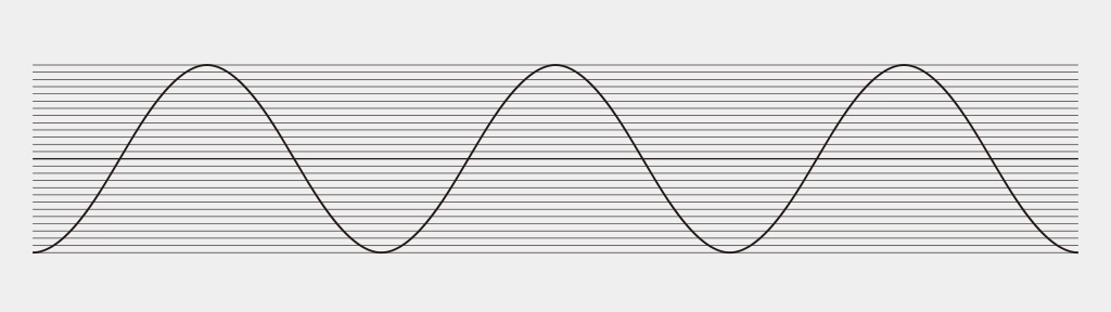
Recorded sound is an analog signal converted into digital data through sampling. Two key metrics define this process: Sampling Rate and Bit Depth.
Sampling Rate
The sampling rate is the “number of times a signal is measured per second,” expressed in Hertz (Hz). Standard CD quality is 44.1 kHz, meaning it measures 44,100 times per second.
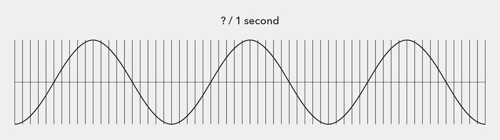
According to the Nyquist Theorem (Sampling Theorem), to accurately convert an analog signal into digital, the sampling rate must be at least twice the highest frequency present in the signal.
In field recording, you set the sampling rate on your device. While the choice depends on the intended use, recording at “Hi-Res” rates like 96 kHz or 192 kHz provides greater flexibility for post-processing, though it results in larger file sizes.
- Unit: Hz. CD quality is 44.1 kHz.
- To accurately record the human hearing range (~20 kHz), double that frequency is required (Nyquist Theorem).
Bit Depth
Bit depth represents the amount of information per sample. Higher bit depth allows for capturing finer nuances and recording with high fidelity while minimizing distortion noise. Note that bit depth does not relate to frequency resolution.
The analog counterpart to bit depth is Dynamic Range—the ratio between the maximum and minimum signal values a system can handle. Higher bit depth increases the resolution of the amplitude, widening the dynamic range:
- 8-bit: Approx. 20 × log10(2⁸) ≈ 48dB
- 16-bit: Approx. 20 × log10(2¹⁶) ≈ 96dB(CD Standard)
- 24-bit: Approx. 20 × log10(2²⁴) ≈ 144dB
- 32-bit float: Theoretically offers a massive dynamic range. Because it uses a different representation method than fixed-point, it is highly resistant to clipping and provides immense freedom in post-production.
Higher bit depth increases the potential to express a wider dynamic range. However, other factors like the noise floor and saturation levels also affect the final dynamic range. Bit depth can be thought of as the “fineness of the container” for expressing dynamic range.
Common field recording standards are 24-bit or 32-bit float. 32-bit float, now common in modern devices, performs extremely fine division, including decimals. This is covered in another article: “Introduction to Field Recording | 32-bit float Recording.”
- Indicates amplitude resolution per sample (16bit = 2¹⁶levels).
- Relates to dynamic range; 24-bit or 32-bit float is recommended for ambient sounds.
In summary, higher sampling rates enable more accurate recording of frequency components, while higher bit depths allow for more nuanced representation of sound pressure variations.
Understanding Ambient Sound and Microphone Placement (Common Miking Techniques)
- Microphone Placement According to Environmental Characteristics
- In open fields, placing microphones over a wide area captures the overall sound naturally.
- In dense forests or urban settings, focusing on specific directions can reduce unwanted noise.
- Impact of Microphone Height and Angle
- Placing microphones close to the ground effectively captures low-frequency sounds like rumbles or animal footsteps.
- Higher placements are suitable for capturing wind sounds or high-frequency elements.
Stereo recording typically involves spacing two microphones a few meters away from the target, depending on the recording content.

- A-B Technique
The most basic method. Two omnidirectional microphones are placed parallel to each other, creating time differences in sound arrival to produce a stereo effect. This setup captures a wide sound field with minimal interference. - X-Y Technique
Uses two unidirectional microphones placed at a 90-degree angle, overlapping at the same point. This enhances positional accuracy and captures sound naturally without an overly wide sound field. - ORTF/NOS Techniques
Both use two unidirectional microphones. ORTF places them 17 cm apart at a 110-degree angle, while NOS places them 30 cm apart at a 90-degree angle. These setups excel at realistically reproducing the sound field, balancing volume and stereo imaging. ORTF was developed by the French Broadcasting Corporation, and NOS by the Dutch Broadcasting Corporation.
Experiment
Record the same sound at “44.1kHz / 16-bit” and “96kHz / 24-bit” to compare. Experience the expanded sound field and subtle differences with higher sampling rates.
Gain Structure and Noise Management
In field recording, adjusting the input recording level is crucial. Proper level settings significantly affect sound quality. Levels that are too low increase noise, while levels that are too high cause clipping.
Ideal Level Design
Adjust levels so peaks fall between -6 and -12 dBFS. In field recording, aiming for -12 dBFS provides a margin for sudden loud sounds.
- Keep peaks between -6 and -12 dBFS.
- Secure more margin in environments with a wide dynamic range.
Managing Noise
Noise is inevitable in the field. Wind is the primary enemy; use windjammers, shock mounts, and protectors to mitigate physical vibrations and wind interference. Be aware of electromagnetic interference (EMI) in electronic environments. While complete elimination is impossible, monitoring with headphones and “enjoying the noise itself” can be part of the process.
- Avoid wind and vibration noise with windjammers and shock mounts.
- Always monitor with earphones and judge using both your “ears” and the “meters.”
Sampling Theory and Aliasing
Sampling Theory
This is the theoretical foundation for converting analog waves (continuous) into digital data (discrete). To digitize, values are taken as “samples” at fixed intervals.
Aliasing
Aliasing is a “frequency misidentification (folding error)” that occurs when the sampling rate is insufficient. If the rate is below the Nyquist frequency, high-frequency sounds are incorrectly recorded as low-frequency components, causing noise or distortion. Recorders typically have an Anti-aliasing filter to remove these components before sampling.
| Rate Selection | 44.1 kHz+ recommended. 96 kHz+ is effective for bird songs/insects. |
| Hi-Res Recording | 192 kHz captures ultrasonic spatial info. |
| Equipment | Ensure recorders/mics have proper frequency response/filters. |
| Downsampling | Use proper resampling (interpolation/filters) when lowering rates. |
How Digital Filters and EQ Work
Digital filters and EQ (Equalizers) are tools used to process and optimize recorded sound. They are used to control the frequency components of sound, emphasizing or removing them depending on the purpose.
Digital Filter
A digital filter is a process that uses Digital Signal Processing (DSP) to pass or block specific frequency bands. The main types of filters are as follows:
| Filter Type | Function | Example Use |
|---|---|---|
| Low-Pass Filter (LPF) | Attenuates frequencies higher than the specified cutoff frequency. | Removal of high-frequency noise, mitigation of wind hiss. |
| High-Pass Filter (HPF) | Attenuates frequencies lower than the specified cutoff frequency. | Removal of microphone proximity effect and low-frequency noise (traffic, wind). |
| Band-Pass Filter (BPF) | Passes only a specific frequency band. | Emphasizing only the target sound, such as bird songs. |
| Band-Stop (Notch) Filter | Removes a specific frequency band. | Removal of hum noise (50Hz/60Hz), etc. |
FIR and IIR Filters
FIR (Finite Impulse Response) filters and IIR (Infinite Impulse Response) filters are the two basic forms of digital filters. Each has its own characteristics, advantages, and disadvantages, and they are used differently depending on the application.
- FIR (Finite Impulse Response): Stable and highly accurate. Maintains linear phase.
- IIR (Infinite Impulse Response): Efficient and behaves similarly to analog circuits.
| Item | FIR Filter | IIR Filter |
|---|---|---|
| Stability | Always stable | Potential to become unstable |
| Phase Characteristics | Linear phase is possible (no waveform distortion) | May involve phase distortion |
| Feedback | None (Output depends only on input) | Yes (Output includes past outputs) |
| Computational Load | High (High cost) | Low (Efficient) |
| Ease of Implementation | Easy | Requires caution for stabilization and design |
| Use Cases | Audio/image processing where high quality is required | Real-time processing, control systems, etc. |
| Purpose | Recommended Filter | Reason |
|---|---|---|
| Sound shaping or clean editing after recording | FIR | Advantageous when you want to remove specific frequencies without changing the waveform (e.g., cleanly extracting bird voices). |
| Real-time processing (Live noise removal, monitoring during recording) | IIR | Suitable for applications requiring immediate response with light processing. |
EQ (Equalizer)
An EQ (Equalizer) is a tool that allows you to freely boost (amplify) or cut (attenuate) frequency bands of sound, and it is a type of digital filter. The main types of EQ are as follows:
| Type | Characteristics | Use Case |
|---|---|---|
| Parametric EQ | Frequency, bandwidth, and gain can be set freely. | Precise sound creation and removal of unwanted sounds. |
| Graphic EQ | Adjusts pre-determined frequency bands with fixed sliders. | Convenient for live sound and simple adjustments. |
| Shelving EQ (Low/High Shelf) | Boosts/cuts everything below (or above) a specified frequency at once. | Adjusting “airiness” (highs) or deep bass (lows). |
In field recording, there are various types of noise depending on the situation and the recording subject, so settings are made with their use in mind.
| Situation | EQ/Filter to Use | Reason |
|---|---|---|
| Source containing wind noise | High-Pass Filter | Cut low-frequency wind noise (e.g., below 80–150Hz). |
| Wanting to extract only bird songs | Band-Pass or Parametric EQ | Emphasize bird voices while suppressing surrounding noise. |
| Deep bass from distant cars resonating | Low-Pass or EQ | Clear the sound field by cutting low frequencies. |
| Electromagnetic noise present | Notch Filter | Remove specific frequencies such as 50Hz/60Hz hum noise. |
Experiment
Implement these using audio editing software or programming tools such as Processing or openFrameworks. Use filters to extract only specific bands and visually observe the structure of the sound.
Experiment
- Mic Comparison: Record with multiple mics and compare waveforms/spectrums.
- Gain Test: Find optimal levels in different environments (nature vs. city).
- Simple DSP Code: Implement real-time filters in Processing or openFrameworks.
- Analysis: Use editing software with spectral display to understand frequency traits.
“Judgment” is a Hybrid of Knowledge and Experience
By understanding recording equipment and digital signal processing, your decisions—“Why this setting?” or “Why this mic?”—move from guesswork to clear, evidence-based choices.
Recommended Book
The Soundscape – R. Murray Schafer

This book introduces the idea of the “soundscape”—a term the author created—to describe the sounds that surround us in everyday life. From the natural sounds of the past to the noise of modern cities and machines, our acoustic environment has become increasingly complex.
The author argues that as noise levels rise, our ability to truly listen and notice subtle sounds has declined. He encourages us to become more aware of the sounds around us, to listen more closely, and to recognize the difference between enriching sounds and harmful noise.
Just as we’re concerned about air and water pollution, we should also care about sound pollution. The book offers ways to classify sounds, judge their quality, and includes simple exercises and “soundwalks” to help us tune in. It’s a thoughtful guide to understanding our sonic world—past, present, and future.
—–
► The Soundscape – R. Murray Schafer
Publication date: October 1, 1993
BGD_SOUNDS (barbe_generative_diary SOUNDS)
barbe_generative_diary SOUNDS will start sharing and selling a variety of field recordings collected for use in my artwork “Sound Visualization” experiments. All sounds are royalty-free.
Follow us to be the first to hear when we release new sound library:
